Custom Search
WELCOME to Free Project Circuit Diagram
Subscribe to updates

World Visitor Map


counter

Project Directories

Showing posts with label Power Supply. Show all posts

Saturday, October 8, 2011

Battery Powered Burglar Alarm Circuit

Here’s a design circuit for single zone alarm - with independently adjustable Exit, Entry and Siren Cut-Off timers. It will accommodate the usual types of normally-closed input devices - such as magnetic-reed contacts, foil tape and PIRs. This is the figure of the circuit;


The alarm is easy to operate. Sw1 can be any type of two-way switch. If the Buzzer sounds when you switch the alarm on - the normally-closed loop is open. Switch off again - and check the building for open doors or windows. If the Buzzer does not sound - the loop is intact. Depending on the setting of R3 - you have up to about a minute to leave the building. As you do so - the Buzzer will sound. When you close the door behind you - it should stop sounding. This confirms that the loop has been restored within the time allowed. When you return and open the door - the Buzzer will sound. Depending on the setting of R4 - you have up to about a minute to switch the alarm off. If you fail to do so - the Siren will sound. Depending on the setting of R5 - the Siren will sound for up to about 20-minutes. Then it will switch off - and remain off. Of course - you can stop the noise at any time by moving Sw1 to the "off" position.

Thursday, January 6, 2011

3A Simple Switcher Power Module Using 20V Maximum Input Voltage

This is a design circuit for power module that is an easy-to-use step-down DC-DC solution capable of driving up to 3A load with exceptional power conversion efficiency, line and load regulation, and output accuracy. The LMZ12003 is available in an innovative package that enhances thermal performance and allows for hand or machine soldering. This is the figure of the circuit;


The LMZ12003 can accept an input voltage rail between 4.5V and 20V and deliver an adjustable and highly accurate output voltage as low as 0.8V. The LMZ12003 only requires three external resistors and four external capacitors to complete the power solution. The LMZ12003 is a reliable and robust design with the following protection features: thermal shutdown, input under-voltage lockout, output over-voltage protection, short-circuit protection, output current limit, and allows startup into a pre-biased output. A single resistor adjusts the switching frequency up to 1 MHz.

Monday, November 1, 2010

Basic Uninterruptible Power Supply Circuit


This is a design circuit for basic interruptible Power Supply Circuit consist of regular power supply adapter and battery connection. This basic system is a “hot” battery connection, meaning that there is no switching mechanism in connecting and disconnecting the battery, the battery is always connected! This hot connection is very simple to implement and very robust because there would be no switching delay, the output voltage will be 100% continue if a power down happens, until the battery loose its capacity. This is the figure of the circuit;


When the power line is normal, the current from the main adapter (transformer-rectifier diode bridge-filter capacitor) flow to the load through D3, and the battery is charged via R1 and D1. The diode D2 prevent the current at D3 output to be shorted by the empty battery in the normal power line condition. If the power down happens then the battery will supply the current to the load through D 2. Use a 15V AC output transformer for 12 volt lead acid battery. LED1 will indicate if the power line is normal. LED D1 will turn off if the power line is down.

Saturday, October 23, 2010

Analog Tremolo (Guitar) Sound Effect Circuit


This is the circuit for the tremolo effect produce an amplitude modulated signal. Unlike vibrato effect that produce frequency modulated, this tremolo effect will produce the same effect as quickly turning up-ad-down your volume control repeatedly. This is the figure of the circuit;
Q1 is general small signal audio transistor, you can use almost any type of NPN small signal transistors. MFC3304P is a voltage controlled amplifier IC with negative control, it might be difficult to find these days, but I think you can replace with general OTA (operational trans-conductance amplifier), with the appropriate biasing circuit off course. Just bias the current control of an OTA through a resistor, and add the C4 modulator signal at the control pin of the OTA.

Sunday, September 19, 2010

Passive Treble Control Circuit for Guitar Pedal


The R1/C1 network makes a low pass filter when the wiper is at the grounded end of the tone pot, and there is a treble cut. The C1 cap bypasses R2 when the wiper is adjusted so that it is at the top end of the pot and it creates a treble boost. This is the figure of the circuit;


The 100k output volume and the 100k tone pot are always in parallel as a constant load. It’s suggested to used a linear taper pot for the tone control and a log (audio) taper for the volume control. Suggested values for initial experimentation are R1=10k, R2=47k, and C1=0.022uF. Some signal loss, as with any passive network is the limitation of this combined tone control. However, many guitar pedal designs have strong enough output signal level, and this tone control is an excellent option for those circuits with enough drive.

Sunday, August 15, 2010

Stabilizer Circuit


This is a circuit for high quality power supply with a continuously variable stabilized output adjustable at any value between 0 and 30VDC. The circuit also incorporates an electronic output current limiter that effectively controls the output current from a few milliamperes (2 mA) to the maximum output of three amperes that the circuit can deliver. This is the figure of the circuit;


This feature makes this power supply indispensable in the experimenters laboratory as it is possible to limit the current to the typical maximum that a circuit under test may require, and power it up then, without any fear that it may be damaged if something goes wrong. There is also a visual indication that the current limiter is in operation so that you can see at a glance that your circuit is exceeding or not its preset limits.

Wednesday, December 9, 2009

Adjustable Power Supply Using LM723

This is a design circuit for variable or adjustable power supply. This variable power supply is a simple but reliable one based on an integrated voltage regulator LM723. Here’s figure of the power supply circuit.


The R2 is set the output voltage. The maximum flow is determined by the value of R3, the excessive current in the circuit protection senses R3 and LM723 voltage output stage begins to close off this fast voltage approaches 0.65 V. In this way the current through R3 can never exceed 0.65/R3, even if output is shorted. C3 and C4, both ceramic, should be placed as close as possible to the integrated circuit, because the LM723 can be vulnerable to unwanted oscillations. The LM723 works with the input DC voltage V and IC 9,5-40 itself can be the source of about 150 mA if the output voltage is not more than 6-7 V below the input. When the external pass transistor is used (in the usual emitter-follower mode), the base-emitter of T1 is a significant resistance and the output stage of integrated circuits is relatively light load. All the current drawn by the load through a T1 and it decreases the amount of power that is proportional to the current and the difference between input and output DC voltage.

Source: www.zen22142.zen.co.uk

Friday, December 4, 2009

Dual Rail Power Supply Circuit

This is a conventional type of power supply. Here’s the schematic of this circuit.


The power is applied through the step-down transformer (230/12-0-12V/500mA). The DC proportional to the charging input voltage is obtained from bridge rectifier. Two electrical are there to bypass any spikes present. Bridge is capable of handling currents up to 1 Amp.

Thursday, December 3, 2009

Regulated DC Power Supply Circuit

This is a design circuit for regulated DC power supply. In this circuit is using short circuit protection and with current limiter. This is the figure of the circuit.


This PSU has been especially designed for current-hungry ham radio transceivers. It delivers safely around 20Amps at 13.8V. For lower currents, a separate current limiting output, capable of 15ma up to a total of 20A has been added. The power transformer should be capable to deliver at least 25A at 17.5 to 20V. The lower the voltage, the lower power dissipation. The rectified current will be "ironed" by C1, whose capacity should not be less than 40.000uF, (a golden rule of around 2000uF/A), but we recommend 50.000uF. This capacity can be built up by several smaller capacitors in parallel. The D2, R3 and B-E connection of the Q4 will sense the Uds voltage of the FET1. When the voltage rises enough, the Q4 will shortcut the FET1 gate to mass, and cut the current flow through the FET 1 off.

Wednesday, November 25, 2009

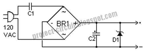
Simple Transformer Power Supply

This is the design for power supply. . This supply uses no heavy step down transformer and has an extremely low parts count. The circuit can be built very small and can supply small currents for small projects. This is the figure of the circuit.


The value of C1 can be increased to increase the amount of current the circuit can supply. With the values shown, the circuit can supply up to about 15mA. Remember to increase the size of C2 also. You may want to add a resistor in series with C1 to limit current if the circuit is plugged in and the mains is at its full voltage. If you are running the circuit from 220VAC, then use a capacitor rated at greater than 400V for C1. If you want isolation from the AC line, you can connect up a small isolation transformer at the inputs of the circuit. Small 600ohm audio transformers work nicely.

Part:
C1 0.39uF 250V Capacitor
C2 220uF 25V Electrolytic Capacitor
D1 1N4741 11V Zener Diode
BR1 1 Amp 200V Bridge Rectifier

High Voltage and Low Current Supply

This is the design for power supply that is a very useful source which can be effectively used in many applications like biasing of gas-discharge tubes and radiation detectors etc. This is the figure of the circuit.


In this configuration, the primary winding and the feedback winding are arranged such that a sustaining oscillation is ensured once the supply is switched on. The waveform’s duty cycle is asymmetrical, but it is not very important in this application. Please note that if the oscillations do not occur at the ‘switch-on’ time, the transformer winding terminals of the feedback or the primary winding (but not both) should be reversed. The primary oscillation amplitude is about 24V(p-p). This gets amplified with the large step-up ratio of the transformer and we get about 800V(p-p) across the secondary. A simple series voltage multiplier (known as Cockroft-Walton circuit) is used to boost up this voltage in steps to give a final DC of about 2 kV. The output voltage, however, is not very well regulated. But if there is a constant load, the final voltage can be adjusted by varying the supply voltage.

DC to AC Inverter

This is design circuit for inverter. This circuit is convert DC to AC voltage. This circuit is work based on 555 IC. This is the figure of the circuit.


The work of the circuit is producing high voltage output and frequency. The function of the IC is as low frequency oscillator and tuned for frequency 50 to 60 Hz. For adjustment is using potentiometer R4. The IC feeds the output to amplified using TIP to the input by transformer. The capacitor and the coil is used as assuring the effectively sine wave.

Sunday, October 18, 2009

Symmetric Power Supply without CT Transformer

This is a kind design of power supply. It is like a center tapped transformer with a bridge diode is common solution to provide symmetric supply, but we can actually do it with simple solution, using a voltage double - rectifier diodes. This is the figure of the circuit.


The capacitor need to be large because the rectifying is half wave, so you can avoid power line hum. With the component values shown, the power supply is capable supplying 10mA at ripple voltage about 0.2V (peak to peak). The voltage ripple can be approximated by Vripple = (20 x I)/C, where I is the current drawn by the load in mA, and C is the capacitance in uF (micro farad).

Monday, October 12, 2009

Basic Symmetric Power Supply Circuit

The circuit below is the basic design schematic for standard symmetrical power supply. If your circuit need high current then this circuit is suitable. This circuit is consist of some part component that can buy in all every electro store. The component that is used only transformer and diode. This is the figure of the circuit.


You need a center-tapped transformer to build this symmetric power supply. This power supply circuit is widely used in op-amp application, as well as in high-rated power amplifier. The operation of the circuit is control by diode or bridge diode.

Monday, September 28, 2009

Universal Power Supply Circuit Using LM371

This is a design circuit for a power supply, but this design is universal power supply. This circuit is using LM371 for control operation. This is the figure of the circuit.


The Universal Power Supply output voltage can be set to anywhere in the range 1.5V to 30V by selecting two resistances. By using a potentiometer, R2, as one of the resistors you can dial up the output voltage wanted. Either AC or DC input can be supplied to the PCB via a socket or terminal block. Connection can be either way around. This is because we have provided a bridge rectifier on board. The input DC voltage to the regulator must be at least 2.5V above the required output voltage. An off/on switch is provided. The LM317 will provide slightly higher output voltages than 30 volts. To be safe for continuous operation the maximal input DC voltage to the regulator should not be over 33V. With a 2.5V to 3.0V drop across the regulator this will give a regulated output of 30V. You can draw up to 1.5A from the LM317.

When external capacitors are used with any IC regulator it is good practice to add protection diodes to prevent the capacitors discharging back into the regulator in the event of abnormal operating conditions, like a sudden short circuit on the input or the output, or a back emf from an inductive load. That is the function of D1 and D2.


Sponsor

Powered By Blogger