


This is a design project for
guitar effect called Wah Pedal Effect. Wah Pedal has been desing around since
at least the early 60’s. The Vox is
one of brand guitar effect which is give
beautiful sound and simple, only a couple of transistors and an inductor. The
really pertinent question that had
puzzled many people - including especially me - is how do you get a moving
resonant frequency out of a fixed inductor and a fixed capacitor? How does that
silly two-transistor Wah Pedal circuit get a moving band pass out of a circuit
that changes neither the inductor value or the capacitor, but only what amounts
to a volume pot? This is the figure of
the circuit;
World Visitor Map
Showing posts with label Sensor. Show all posts
Showing posts with label Sensor. Show all posts
Monday, June 8, 2020

Saturday, August 27, 2011
True Stereo Indicator Circuit for Detects L-R Signal Difference
This circuit is true stereo indicator is different from what we usually find on FM radio receiver, which is usually a pilot tone detector. A stereo broadcast from FM radio station contain pilot tone, but a presence of pilot tone doesn’t necessarily a stereo broadcast signal since a mono FM transmitter ca broadcast pilot tone as well. This is the figure of the circuit;

Since this circuit to detect the difference between left and right channel, this circuit can detect a real stereophonic programs. When there is no difference between R and L input signals, the output A1 and output A2 is at the same potential. That will make a a virtual ground rail at half the supply voltage. The A1 will supply a negative or positive voltage when A1 detects a difference between R and L input signals with respect to the virtual ground rail. The C4 will be charged via D2 an C3 via D1. The LED is turned on by the comparator A3/A4 via OR circuit D3/D4. The input signal level should be greater than 100mV to compensate for the drop across D2 or D1. P1 is used to adjust the sensitivity of stereo indicator.
Monday, January 24, 2011
Ice Warning And Light Reminder Circuit
This is a design circuit for very simple ice warning and lights reminder electronic. This device will tell a driver if his lights should be on and will warn him if the outside temperature is nearing zero by lighting a LED and sounding a buzzer. This is the figure of the circuit;
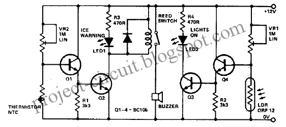
Using the VR1 you can adjusts sensitivity for temperature and using VR2 you can adjust sensitivity for the light. Both thermistor and LDR should be well protected. More high gain NPN transistors will work for this electronic project. For this electronic project you can use BC108 type transistor or some other NPN high gain transistor. This ice warning and lights reminder electronic project must be powered from a 12 volt DC power supply circuit.
Thursday, January 20, 2011
Flame Detector Using Platinum-Rhodium Thermocouple
In furnace operation, it is necessary to make sure that the fuel or gas is ignited properly by detecting the flame. If there’s no flame detected, the situation can be dangerous if the furnace is flooded with explosive gas, so the fuel/gas supply valve should be closed automatically to avoid catastrophic disaster. A thermocouple can be use to detect flame. This is the figure of the circuit;

A platinum-rhodium thermocouple produce 8mV output at 800 °C. You can see the thermocouple is connected directly to the positive and negative inputs, look like there’s no threshold, but wait, the balance input (pin 5) is connected to the reference output and this gives the threshold. [Circuit diagram source: National Semiconductor Application Note]
Saturday, November 20, 2010
Buffering TMP01 Temperature Sensor Circuit
This is a circuit for a buffer circuit for TMP01 Temperature Sensor. The output of this sensor is a low impedance dc output voltage with a 5 mV/K temperature coefficient. This sensor can be used in multiple control and measurement applications. The buffered VPTAT voltage output can drive 500 µA into 50 pF (maximum). This is the figure of the circuit;

To minimize loading that could create dissipation-induced temperature sensing errors and to ensure accuracy, an external amplifier is used in this circuit. The circuit can drive over 10 mA. It still stable under capacitive loads of up to 0.1 µF. [Circuit diagram source: analog.com]
Sunday, September 5, 2010
AD586/597 Temperature Transducer (Sensor) Circuit
This is a circuit for a stand alone temperature transducer/sensor circuit. This device uses The AD596/AD597, employing its internal junction compensation temperature sensor inside. This device can be used as temperature sensor by omitting the thermocouple and connecting the inputs (Pins 1 and 2) to common. This is the figure of the circuit;
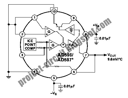
The output will reflect the compensation voltage and the AD596/AD597 temperature will be indicated by the output. the AD596/AD597 will be operated over the full extended –55°C to +125°C temperature range. This device has output scaling of 10.1 mV per°C with the AD597 and 9.6 mV per °C with the AD596. when AD596 is used in temperature sensing mode, it will read slightly high, because there is 42mV offset.
Wednesday, April 7, 2010
Avoiding Electrolysis For Water Level Detector Probes Using Alternating Current Detection
Electrolysis process has been the primary cause of your water level detector probes, and you can avoid this by sensing the current by this probe using alternating current. In alternating current, the electrolysis process will be reversed for every alternating cycles, making the probe will last longer to survive from corrosion. This is the figure of the electronic circuit for this alternating current sensing for water level detector.

The whole circuit consists of oscillator and detector. The oscillator is build around U1A. The capacitor C2 is inserted between the oscillator output and the probe to block DC signal, same as the C3 capacitor function. When the probe is submersed under water, an alternating current generated by the oscillator will flow through C2, probes, and C3. The alternating current from C3 is then rectified by D2 and filtered by C4 to get back the DC voltage. The diode D1 is provided to give the back flow path for the alternating current. Without D1, the alternating current won’t flow since the D2 diode only permit the current to flow for one direction. The DC level is detected on C4 and then its trigger the U1B gate to turn on the relay. You can control a water pump using the relay output to turn on the pump if the water level is below the probes, and turn off when they’re submersed.

The whole circuit consists of oscillator and detector. The oscillator is build around U1A. The capacitor C2 is inserted between the oscillator output and the probe to block DC signal, same as the C3 capacitor function. When the probe is submersed under water, an alternating current generated by the oscillator will flow through C2, probes, and C3. The alternating current from C3 is then rectified by D2 and filtered by C4 to get back the DC voltage. The diode D1 is provided to give the back flow path for the alternating current. Without D1, the alternating current won’t flow since the D2 diode only permit the current to flow for one direction. The DC level is detected on C4 and then its trigger the U1B gate to turn on the relay. You can control a water pump using the relay output to turn on the pump if the water level is below the probes, and turn off when they’re submersed.
Thursday, March 25, 2010
Isolated Temperature Sensor Circuit
In some temperature-sensing applications there are some problems caused by the placement of sensors on location where the potential is very different from that of the data-acquisition-system common. So the operating temperature sensor must be isolated from its data-acquisition system galvanically. And the power’s source for the sensor was isolated. This circuit is designed to solve that problem. It provides power and isolation for a temperature sensor. This is the figure of the circuit.

This circuit is use the MAX845 (IC1) as a power transformer driver. The power of the temperature sensor is generated by the secondary winding from transformer that feeds a Graetz bridge rectifier. This circuit uses the MAX6576 (IC2) as temperature sensor that is provides a digital output whose period encodes the temperature (10µs/°K to 640µs/°K) and isolated by transformer. The MAX6576 was chosen because it combines the temperature sensor, signal-processing electronics, and easy-to-use digital I/O interface in a single low-cost package. It draws very little current from a single supply voltage. The MAX6576 is operated in the range +3V to +5V but it can maintain its accuracy specs.
[Circuit schematic source: maxim-ic.com]

This circuit is use the MAX845 (IC1) as a power transformer driver. The power of the temperature sensor is generated by the secondary winding from transformer that feeds a Graetz bridge rectifier. This circuit uses the MAX6576 (IC2) as temperature sensor that is provides a digital output whose period encodes the temperature (10µs/°K to 640µs/°K) and isolated by transformer. The MAX6576 was chosen because it combines the temperature sensor, signal-processing electronics, and easy-to-use digital I/O interface in a single low-cost package. It draws very little current from a single supply voltage. The MAX6576 is operated in the range +3V to +5V but it can maintain its accuracy specs.
[Circuit schematic source: maxim-ic.com]
Monday, December 14, 2009
Water Level Alert Circuit
This is a circuit that can be use when the water contained into a recipient has reached the desired level. This circuit is work with based on 555 timer IC. This is the figure of the circuit.

C1, a 555 CMos timer chip, is wired as an astable multi vibrator whose operating frequency is set by C1, R1 and R2, plus the resistance presented by water across the probes. If the resistance across the probes is zero (i.e. probes shorted), the output frequency will be about 3Hz and the sounder will beep (or the LED will flash) about three times per second. As water usually presents a certain amount of resistance, the actual oscillation frequency will be lower: less than one beep/flash per second. As probes will be increasingly immersed in water, the resistance across them will decrease and the oscillation frequency of IC1 will increase. This means that a rough aural or visual indication of the level reached by water will be available. If a LED is chosen as the alert, C2, D1 and D2 must be added to the circuit in order to double the output voltage, thus allowing proper LED operation (see the rightmost part of the schematics). Interesting features of this circuit are 1.5V supply and ultra-low current consumption: 40µA in stand-by and 0.5mA in operation. This allows a single AAA alkaline cell to last several years and the saving of the power on/off switch.
Part:
R1_______________1K 1/4W Resistor
R2_____________100K 1/4W Resistor (See Notes)
C1_______________2µ2 50V Electrolytic Capacitor
C2_____________220µF 25V Electrolytic Capacitor (See Notes)
D1______________5 or 10mm. Ultra-bright red LED (See Notes)
D2____________1N5819 40V 1A Schottky-barrier Diode (See Notes)
IC1_____________7555 or TS555CN CMos Timer IC
BZ1____________Piezo sounder (incorporating 3KHz oscillator)
B1_____________1.5V Battery (AAA or AA cell etc.)

C1, a 555 CMos timer chip, is wired as an astable multi vibrator whose operating frequency is set by C1, R1 and R2, plus the resistance presented by water across the probes. If the resistance across the probes is zero (i.e. probes shorted), the output frequency will be about 3Hz and the sounder will beep (or the LED will flash) about three times per second. As water usually presents a certain amount of resistance, the actual oscillation frequency will be lower: less than one beep/flash per second. As probes will be increasingly immersed in water, the resistance across them will decrease and the oscillation frequency of IC1 will increase. This means that a rough aural or visual indication of the level reached by water will be available. If a LED is chosen as the alert, C2, D1 and D2 must be added to the circuit in order to double the output voltage, thus allowing proper LED operation (see the rightmost part of the schematics). Interesting features of this circuit are 1.5V supply and ultra-low current consumption: 40µA in stand-by and 0.5mA in operation. This allows a single AAA alkaline cell to last several years and the saving of the power on/off switch.
Part:
R1_______________1K 1/4W Resistor
R2_____________100K 1/4W Resistor (See Notes)
C1_______________2µ2 50V Electrolytic Capacitor
C2_____________220µF 25V Electrolytic Capacitor (See Notes)
D1______________5 or 10mm. Ultra-bright red LED (See Notes)
D2____________1N5819 40V 1A Schottky-barrier Diode (See Notes)
IC1_____________7555 or TS555CN CMos Timer IC
BZ1____________Piezo sounder (incorporating 3KHz oscillator)
B1_____________1.5V Battery (AAA or AA cell etc.)
Monday, December 7, 2009
Rain Detector Circuit
This is a circuit for alarm that is sensing the water. This circuit is work with based on 555 astable multi vibrator that is used here which gives a tone of about 1kHz upon detecting water. Here’s the circuit diagram.

It has to placed making an angle of about 30 - 45 degrees to the ground. This makes the rain water to flow through it to the ground and prevents the alarm from going on due to the stored water on the sensor. The metal used to make the sensor has to be aluminum and not copper. This is because copper forms a blue oxide on its layer on prolonged exposure to moisture and has to be cleaned regularly. The aluminum foils may be secured to the wooden / plastic board via epoxy adhesive or small screws.
The contact X and Y from the sensor may be obtained by small crocodile clips or you may use screws.

It has to placed making an angle of about 30 - 45 degrees to the ground. This makes the rain water to flow through it to the ground and prevents the alarm from going on due to the stored water on the sensor. The metal used to make the sensor has to be aluminum and not copper. This is because copper forms a blue oxide on its layer on prolonged exposure to moisture and has to be cleaned regularly. The aluminum foils may be secured to the wooden / plastic board via epoxy adhesive or small screws.
The contact X and Y from the sensor may be obtained by small crocodile clips or you may use screws.
Wednesday, November 11, 2009
Wide Band Zero Cross Detector Circuit
This is circuit that can be used to convert a low amplitude 40 KHz signal into a clean square wave signal. This circuit is call wide band zero cross detector. This is the figure of the circuit.

This circuit will work with inputs as small as 5mv peak-to-peak or as large as 3 volts peak to peak. The input frequency can range from a few kilohertz to about 150 KHz. This circuit is work with based on LM393. [Circuit source: Dave Johnson].

This circuit will work with inputs as small as 5mv peak-to-peak or as large as 3 volts peak to peak. The input frequency can range from a few kilohertz to about 150 KHz. This circuit is work with based on LM393. [Circuit source: Dave Johnson].
Room Noise Detector Circuit
This circuit is called the Room Noise Detector, which is intended to signal, through a flashing LED, which exceeds the threshold specified in the room noise, chosen from three fixed levels, namely 50, 70 & 85 dB.

This circuit diagram using two Op-amps, which provides the circuits required to obtain a voice-picked by a miniature electric microphone to drive a LED. SW1 to the first position in the circuit is not active. Second, third and fourth position in the power circuit and set the input sensitivity threshold to 85, 70 & 50 dB respectively.
Part :
R1 = 10K
R2,R3 = 22K
R4 = 100K
R5,R9,R10 = 56K
R6 = 5K6
R7 = 560R
R8 = 2K2
R11 = 1K
R12 = 33K
R13 = 330R
C1 = 100nF
C2 = 10µF 25V
C3 = 470µF 25V
C4 = 47µF 25V
D1 = Red LED
IC1 = LM358
Q1 = BC327
MIC1 = Miniature electret microphone
B1 = 9V Battery

This circuit diagram using two Op-amps, which provides the circuits required to obtain a voice-picked by a miniature electric microphone to drive a LED. SW1 to the first position in the circuit is not active. Second, third and fourth position in the power circuit and set the input sensitivity threshold to 85, 70 & 50 dB respectively.
Part :
R1 = 10K
R2,R3 = 22K
R4 = 100K
R5,R9,R10 = 56K
R6 = 5K6
R7 = 560R
R8 = 2K2
R11 = 1K
R12 = 33K
R13 = 330R
C1 = 100nF
C2 = 10µF 25V
C3 = 470µF 25V
C4 = 47µF 25V
D1 = Red LED
IC1 = LM358
Q1 = BC327
MIC1 = Miniature electret microphone
B1 = 9V Battery
Audio Power Amplifier Over Temperature Detector
This is a power amplifier for audio that has over temperature detector inside. This circuit is based on LM56 as controller. This is the figure of the circuit.

An audio power amplifier IC is bolted to a heat sink and an LM56 Celsius temperature sensor is mounted on a PC board that is bolted to the heat sink near the power amplifier. To ensure that the sensing element is at the same temperature as the heat sink, the sensor's leads are mounted to pads that have feed through to the back side of the PC board. Since the LM56 is sensing the temperature of the actual PC board the back side of the PC board also has large ground plane to help conduct the heat to the device. The comparator's output goes low if the heat sink temperature rises above a threshold set by R1, R2, and the voltage reference. This fault detection output from the comparator now can be used to turn on a cooling fan. The circuit as shown in design to turn the fan on when heat sink temperature exceeds about 80°C, and to turn the fan off when the heat sink temperature falls below approximately 75°C. [Circuit source: National Semiconductor, Inc Notes].

An audio power amplifier IC is bolted to a heat sink and an LM56 Celsius temperature sensor is mounted on a PC board that is bolted to the heat sink near the power amplifier. To ensure that the sensing element is at the same temperature as the heat sink, the sensor's leads are mounted to pads that have feed through to the back side of the PC board. Since the LM56 is sensing the temperature of the actual PC board the back side of the PC board also has large ground plane to help conduct the heat to the device. The comparator's output goes low if the heat sink temperature rises above a threshold set by R1, R2, and the voltage reference. This fault detection output from the comparator now can be used to turn on a cooling fan. The circuit as shown in design to turn the fan on when heat sink temperature exceeds about 80°C, and to turn the fan off when the heat sink temperature falls below approximately 75°C. [Circuit source: National Semiconductor, Inc Notes].
Tuesday, October 20, 2009
Infra Red Link Circuit
This is a battery powered IR Link which may be used in more than one room. This circuit is built by CMOS IC and transistor. This is the figure of the circuit.

This circuit is not powered directly from the battery. When a remote control signal is received, the energy stored in C2 drives the emitter diode. At the same time, Q1 switches on briefly to allow the battery to recharge C2. The green LED shows that the circuit is transmitting; and the yellow LED confirms that C2 has been topped-up. There is unwanted IR radiation in both daylight and tungsten lighting. To minimize its effect use an opaque housing and do not make the opening too large. The depth of shading required will depend on the lighting conditions. When the source of the unwanted radiation is removed the unit may be reset by interrupting the power supply for a few seconds or by pushing the (optional) reset button. If you do neither then it will reset itself after about an hour when C2 has recharged through R7.

This circuit is not powered directly from the battery. When a remote control signal is received, the energy stored in C2 drives the emitter diode. At the same time, Q1 switches on briefly to allow the battery to recharge C2. The green LED shows that the circuit is transmitting; and the yellow LED confirms that C2 has been topped-up. There is unwanted IR radiation in both daylight and tungsten lighting. To minimize its effect use an opaque housing and do not make the opening too large. The depth of shading required will depend on the lighting conditions. When the source of the unwanted radiation is removed the unit may be reset by interrupting the power supply for a few seconds or by pushing the (optional) reset button. If you do neither then it will reset itself after about an hour when C2 has recharged through R7.
Saturday, October 10, 2009
Touch Switch Circuit Using Logic Gate
This is a touch circuit that is used as a latching circuit to switch a LED ON and OFF by physically touching the ON metal plate or OFF metal plate. This circuit is based on logic gate for control the operation. This is the figure of the circuit.

It is important to ensure that 9V battery is used as its DC source. If one uses the mains supply to step down the voltage using a transformer for rectification and filtering to get the 9V DC supply, ensure that the transformer is designed in such a way that it follows the safety standard requirement of UL. This is important to ensure the safety of the user that is using the metal contacts to ON/OFF the LED.[Schematic diagram source: Electronics Project Design].

It is important to ensure that 9V battery is used as its DC source. If one uses the mains supply to step down the voltage using a transformer for rectification and filtering to get the 9V DC supply, ensure that the transformer is designed in such a way that it follows the safety standard requirement of UL. This is important to ensure the safety of the user that is using the metal contacts to ON/OFF the LED.[Schematic diagram source: Electronics Project Design].
Open Loop Fast Peak Detector Circuit
This is a design schematic for fast peak detector similar but faster than previous peak detector, can be implemented using open loop configuration. This circuit is based on LT1190 IC for operation. This is the figure of the circuit.

In this circuit, operation is begun from D1 is the detector diode and D2 is a level shifting or compensating diode. A load resistor RL is connected to – 5V and an identical bias resistor, RB, is used to bias the compensating diode. This equal value resistor is RL and RB makes sure that the diode drops are equal. Low values of RB and RL (1k to 10k) yield in fast response, at the expense of poor low frequency accuracy. High values of RB and RL provide good low frequency accuracy but cause the amplifier to slew rate limit, resulting in poor high frequency accuracy. A solution can be made by adding a feedback capacitor CFB, which improve the negative slew rate on the (–) input. We can expect is under 15% amplitude error for 2Vpp-6Vpp input at 20MHz, much faster than closed loop design. [Schematic diagram source: Linear Technology Application Notes].

In this circuit, operation is begun from D1 is the detector diode and D2 is a level shifting or compensating diode. A load resistor RL is connected to – 5V and an identical bias resistor, RB, is used to bias the compensating diode. This equal value resistor is RL and RB makes sure that the diode drops are equal. Low values of RB and RL (1k to 10k) yield in fast response, at the expense of poor low frequency accuracy. High values of RB and RL provide good low frequency accuracy but cause the amplifier to slew rate limit, resulting in poor high frequency accuracy. A solution can be made by adding a feedback capacitor CFB, which improve the negative slew rate on the (–) input. We can expect is under 15% amplitude error for 2Vpp-6Vpp input at 20MHz, much faster than closed loop design. [Schematic diagram source: Linear Technology Application Notes].
Fast Pulse Detector Circuit
This circuit is a schematic diagram for a fast pulse detector. At 100 ns or wider pulse width, the detection should be error free. At 60 ns pulse width, the detection error should be under 10%. This circuit is a simple design. This is the figure of the circuit.

This circuit should be used to detect at least 100 ns wide pulse to ensure an error free performance. This circuit is based on LT1190 for the operation.[Schematic diagram source: Linear Technology Application Notes]

This circuit should be used to detect at least 100 ns wide pulse to ensure an error free performance. This circuit is based on LT1190 for the operation.[Schematic diagram source: Linear Technology Application Notes]
Current Loop Transmitter for Temperature Sensor
This is a design for current loop transmitter circuit. Current loop interface has been widely used in industrial environment because it is robustness. Noise resistance and fail detection capability made it suitable for long distant transmission in harsh environment. This circuit provide current loop transmitter for temperature sensor. This is the schematic figure.

In the temperature measurement is done by LM35 temperature sensor chip. You can use general silicone diode such as 1N4001. The current controller function is done by LM317 current/voltage regulator. This circuit will draw a consistent current proportional to the temperature being measured, regardless the supply voltage variation caused by noise or long wire’s temperature-dependent resistance variation.

In the temperature measurement is done by LM35 temperature sensor chip. You can use general silicone diode such as 1N4001. The current controller function is done by LM317 current/voltage regulator. This circuit will draw a consistent current proportional to the temperature being measured, regardless the supply voltage variation caused by noise or long wire’s temperature-dependent resistance variation.
Friday, October 9, 2009
AC Line Current Detector Circuit
This is a simple design for current detector circuit. This circuit will detect AC line currents of about 250 mA or more without making any electrical connections to the line. Current is detected by passing one of the AC lines through an inductive pickup (L1) made with a 1 inch diameter U-bolt wound with 800 turns of #30 - #35 magnet wire. The pickup could be made from other iron type rings or transformer cores that allows enough space to pass one of the AC lines through the center. Only one of the current carrying lines, either the line or the neutral should be put through the center of the pickup to avoid the fields cancelling. This output will amplifier using op-amp.

The magnetic pickup (U-bolt) produces about 4 millivolts peak for a AC line current of 250 mA, or AC load of around 30 watts. The signal from the pickup is raised about 200 times at the output of the op-amp pin 1 which is then peak detected by the capacitor and diode connected to pin 1. The second op-amp is used as a comparator which detects a voltage rise greater than the diode drop. The minimum signal needed to cause the comparator stage output to switch positive is around 800 mV peak which corresponds to about a 30 watt load on the AC line.
The output 1458 op-amp will only swing within a couple volts of ground so a voltage divider (1K/470) is used to reduce the no-signal voltage to about 0.7 volts. An additional diode is added in series with the transistor base to ensure it turns off when the op-amp voltage is 2 volts. You may get a little bit of relay chatter if the AC load is close to the switching point so a larger load of 50 watts or more is recommended. The sensitivity could be increased by adding more turns to the pickup.

The magnetic pickup (U-bolt) produces about 4 millivolts peak for a AC line current of 250 mA, or AC load of around 30 watts. The signal from the pickup is raised about 200 times at the output of the op-amp pin 1 which is then peak detected by the capacitor and diode connected to pin 1. The second op-amp is used as a comparator which detects a voltage rise greater than the diode drop. The minimum signal needed to cause the comparator stage output to switch positive is around 800 mV peak which corresponds to about a 30 watt load on the AC line.
The output 1458 op-amp will only swing within a couple volts of ground so a voltage divider (1K/470) is used to reduce the no-signal voltage to about 0.7 volts. An additional diode is added in series with the transistor base to ensure it turns off when the op-amp voltage is 2 volts. You may get a little bit of relay chatter if the AC load is close to the switching point so a larger load of 50 watts or more is recommended. The sensitivity could be increased by adding more turns to the pickup.
A Photo Sensor Circuit Using LED
This is a simple design for sensor circuit. This circuit is using LED for sensor a light. But, for control operation and amplifier the output is using 1458 IC. This is an op-amp. This is the figure of the circuit.

A circuit that is takes advantage of the photo-voltaic voltage of an ordinary LED. The LED voltage is buffered by a junction FET transistor and then applied to the inverting input of an op-amp with a gain of about 20. This produces a change of about 5 volts at the output from darkness to bright light. The 100K potentiometer can be set so that the output is around 7 volts in darkness and falls to about 2 volts in bright light.

A circuit that is takes advantage of the photo-voltaic voltage of an ordinary LED. The LED voltage is buffered by a junction FET transistor and then applied to the inverting input of an op-amp with a gain of about 20. This produces a change of about 5 volts at the output from darkness to bright light. The 100K potentiometer can be set so that the output is around 7 volts in darkness and falls to about 2 volts in bright light.
Subscribe to:
Posts (Atom)
