Custom Search
WELCOME to Free Project Circuit Diagram
Subscribe to updates

World Visitor Map


counter

Project Directories

Wednesday, November 25, 2009

Simple Transformer Power Supply

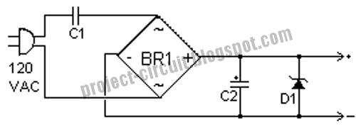
This is the design for power supply. . This supply uses no heavy step down transformer and has an extremely low parts count. The circuit can be built very small and can supply small currents for small projects. This is the figure of the circuit.


The value of C1 can be increased to increase the amount of current the circuit can supply. With the values shown, the circuit can supply up to about 15mA. Remember to increase the size of C2 also. You may want to add a resistor in series with C1 to limit current if the circuit is plugged in and the mains is at its full voltage. If you are running the circuit from 220VAC, then use a capacitor rated at greater than 400V for C1. If you want isolation from the AC line, you can connect up a small isolation transformer at the inputs of the circuit. Small 600ohm audio transformers work nicely.

Part:
C1 0.39uF 250V Capacitor
C2 220uF 25V Electrolytic Capacitor
D1 1N4741 11V Zener Diode
BR1 1 Amp 200V Bridge Rectifier

Simple Pulse Timer Using 555 IC

This is circuit for pulse timer. This is a simple form of the circuit. This circuit is based on 555 timer IC. This is the figure of the circuit.


The operation of the circuit is IC connected as mono-stable multi vibrator. Input pulses are applied to the base transistor. It will conducting the transistor with IC. After those, IC will entry the timing cycle using set the R1xC1.

High Voltage DC Generator

This is a schematic circuit for voltage generator. This circuit is built by 74C14 IC as generator. This is the figure of the circuit.


This circuit is using power supply 12 VDC. The input to the circuit is then amplified to provide 10000 VDC output. Inside the circuit is there a DC to DC converter. The output of the converter is fed into 10 stage using high voltage multiplier to produce 10,000 VDC.

High Voltage and Low Current Supply

This is the design for power supply that is a very useful source which can be effectively used in many applications like biasing of gas-discharge tubes and radiation detectors etc. This is the figure of the circuit.


In this configuration, the primary winding and the feedback winding are arranged such that a sustaining oscillation is ensured once the supply is switched on. The waveform’s duty cycle is asymmetrical, but it is not very important in this application. Please note that if the oscillations do not occur at the ‘switch-on’ time, the transformer winding terminals of the feedback or the primary winding (but not both) should be reversed. The primary oscillation amplitude is about 24V(p-p). This gets amplified with the large step-up ratio of the transformer and we get about 800V(p-p) across the secondary. A simple series voltage multiplier (known as Cockroft-Walton circuit) is used to boost up this voltage in steps to give a final DC of about 2 kV. The output voltage, however, is not very well regulated. But if there is a constant load, the final voltage can be adjusted by varying the supply voltage.

DC to AC Inverter

This is design circuit for inverter. This circuit is convert DC to AC voltage. This circuit is work based on 555 IC. This is the figure of the circuit.


The work of the circuit is producing high voltage output and frequency. The function of the IC is as low frequency oscillator and tuned for frequency 50 to 60 Hz. For adjustment is using potentiometer R4. The IC feeds the output to amplified using TIP to the input by transformer. The capacitor and the coil is used as assuring the effectively sine wave.

6V - 12V Converter Circuit

This circuit is an inverter actually. This circuit is not converter, but it is say as converter cause convert voltage from low to high. This inverter circuit can provide up to 800mA of 12V power from a 6V supply. For example, you could run 12V car accessories in a 6V of the car. The circuit is simple, about 75% efficient and quite useful. This is the figure of the circuit.


This circuit is work based on transistor. L1 is a custom inductor wound with about 80 turns of 0.5mm magnet wire around a toroidal core with a 40mm outside diameter. Different values of D3 can be used to get different output voltages from about 0.6V to around 30V. Note that at higher voltages the circuit might not perform as well and may not produce as much current. You may also need to use a larger C3 for higher voltages and/or higher currents. You can use a larger value for C3 to provide better filtering. The circuit will require about 2A from the 6V supply to provide the full 800mA at 12V.

Part:
R1, R4 2.2K 1/4W Resistor
R2, R3 4.7K 1/4W Resistor
R5 1K 1/4W Resistor
R6 1.5K 1/4W Resistor
R7 33K 1/4W Resistor
R8 10K 1/4W Resistor
C1,C2 0.1uF Ceramic Disc Capacitor
C3 470uF 25V Electrolytic Capcitor
D1 1N914 Diode
D2 1N4004 Diode
D3 12V 400mW Zener Diode
Q1, Q2, Q4 BC547 NPN Transistor
Q3 BD679 NPN Transistor
L1 See Notes MISC1Heatsink for Q3, Binding Posts (for Input / Output), Wire, Board

Wednesday, November 11, 2009

Wide Band Zero Cross Detector Circuit

This is circuit that can be used to convert a low amplitude 40 KHz signal into a clean square wave signal. This circuit is call wide band zero cross detector. This is the figure of the circuit.


This circuit will work with inputs as small as 5mv peak-to-peak or as large as 3 volts peak to peak. The input frequency can range from a few kilohertz to about 150 KHz. This circuit is work with based on LM393. [Circuit source: Dave Johnson].

Room Noise Detector Circuit

This circuit is called the Room Noise Detector, which is intended to signal, through a flashing LED, which exceeds the threshold specified in the room noise, chosen from three fixed levels, namely 50, 70 & 85 dB.


This circuit diagram using two Op-amps, which provides the circuits required to obtain a voice-picked by a miniature electric microphone to drive a LED. SW1 to the first position in the circuit is not active. Second, third and fourth position in the power circuit and set the input sensitivity threshold to 85, 70 & 50 dB respectively.

Part :
R1 = 10K
R2,R3 = 22K
R4 = 100K
R5,R9,R10 = 56K
R6 = 5K6
R7 = 560R
R8 = 2K2
R11 = 1K
R12 = 33K
R13 = 330R
C1 = 100nF
C2 = 10µF 25V
C3 = 470µF 25V
C4 = 47µF 25V
D1 = Red LED
IC1 = LM358
Q1 = BC327
MIC1 = Miniature electret microphone
B1 = 9V Battery

Linear TEC Driver Circuit

This circuit is a driver circuit for thermo electric cooler that is becoming popular because of its robustness and maintenance free characteristic. This driver is capable of delivering ±2A into a TEC. This circuit operates on a single +5V supply and drives the TEC in the most preferred “constant-current” mode. This is the figure of the circuit.


This TEC driver amplifier is a voltage-controlled current source. Constant current drive eliminates the effect of thermal “back EMF” on current through the TEC under dynamic temperature control conditions. Constant-current drive also assures that TEC drive current is independent of production variations in TEC junctions or long-term aging.

Audio Power Amplifier Over Temperature Detector

This is a power amplifier for audio that has over temperature detector inside. This circuit is based on LM56 as controller. This is the figure of the circuit.


An audio power amplifier IC is bolted to a heat sink and an LM56 Celsius temperature sensor is mounted on a PC board that is bolted to the heat sink near the power amplifier. To ensure that the sensing element is at the same temperature as the heat sink, the sensor's leads are mounted to pads that have feed through to the back side of the PC board. Since the LM56 is sensing the temperature of the actual PC board the back side of the PC board also has large ground plane to help conduct the heat to the device. The comparator's output goes low if the heat sink temperature rises above a threshold set by R1, R2, and the voltage reference. This fault detection output from the comparator now can be used to turn on a cooling fan. The circuit as shown in design to turn the fan on when heat sink temperature exceeds about 80°C, and to turn the fan off when the heat sink temperature falls below approximately 75°C. [Circuit source: National Semiconductor, Inc Notes].

10 Watt Linear Amplifier

This is a 10 watt linear amplifier that is capable of delivering over 15 watts into 50 ohms and uses cheap plastic transistors that are used in CB equipment. This circuit is based on transistor. This is the figure of the circuit.


The bias generator transistor, TR4, is marked TIP31 in the circuit diagram, but here you can use just about anything that will fit. You could even use another 2SC2078, if you had money to burn, but more practical components would be TIP41, TIP3055, MJE3055. All that matters is that it will pass up to 1 Ampere and have the correct base details in a TO220 case. The amplifier has a wide bandwidth, from 1.8 MHz through to over 30 MHz. The drive level required is only about 2 - 5 mW under 14 MHz, rising to 10 mW at 30 MHz. You can therefore make a good QRP CW rig with nothing more than this PA and a simple crystal oscillator. [Schematic source: Harry Lythall Notes]

Saturday, November 7, 2009

Video Switch Circuit Using MAX454

This is a video switching circuit. This circuit will provide a dedicated monitor for every installed camera is not efficient, and your CRT monitor might suffer phosphor burn if it used to display static image from only one camera. To display 1, 2, 3, or 4 cameras in one monitor, you need a video switcher circuit. This is the figure of the circuit.


The core of this video switcher is MAX454 video multiplexer-amplifier from MAXIM. Care must be taken when designing the video signal path around this chip. Ground plane or track can be inserted between video signal channels to prevent crosstalk and noise interference. Using socket for IC is bad idea, if you should solder the chip directly to the PCB. You can see a CD4017 sequencer driving the channel indicators (LED1-LED4). The output of this sequencer is not only drives the indicators, but also decoded to 2 bit binary data by D1…D4 to address the MAX454 multiplexer.

Indoor and Outdoor Temperature Controller Circuit

This is a design controller for indoor and outdoor temperature. This circuit is intended for controlling a heating system or central heating plan, keep room temperature constant despite changes in the external one. This is the figure of the circuit.


In principle of work this circuit is when the Q1 to the ground voltage by less than half of supply voltage (determined by R7 & R9), the voltage generated in the R8 and the driver transistors Q2 & Q3-switch on the relay. Two sensors required, one placed outside the home, to sense an external temperature. When Q1 Base voltage to the ground more than half of the voltage supply, caused when one of NTC thermistor low value because of the increase in temperature, voltage does not appear in the R8 and the Relay is not active. C3 allows clean switching of Relay. P1 functions as the main temperature control.

Part:
P1 = 1K Linear Potentiometer
R1 = 10R
R2 = 1K
R3 = 3K3 @ 20°C n.t.c. Thermistor
R4 = 2K2 @ 20°C n.t.c. Thermistor
R5 = 10K
R6 = 3K3
R7,R9 = 4K7
R8 = 470K
R10 = 10K
C1,C2 = 470µF 25V
C3 = 1µF
D1,D2,D4 = 1N4002
D3 = LED Red
Q1 = BC557
Q2 = BC547
Q3 = BC337
RL1 = Relay with SPDT 2A @ 220V switch
Coil Voltage 12V. Coil resistance 200-300 Ohm
T1 = 220V Primary, 12 + 12V Secondary 3VA Mains transformer

Sponsor

Powered By Blogger